Lets sense and move
1. Arduino libraries become a useful starting point to see if your board is working or not. Though they take up space on the chip and don't allow too many things to be done within them.
2. I have started to modify Neil's code and get a better grasp of AVR 'C' programming.
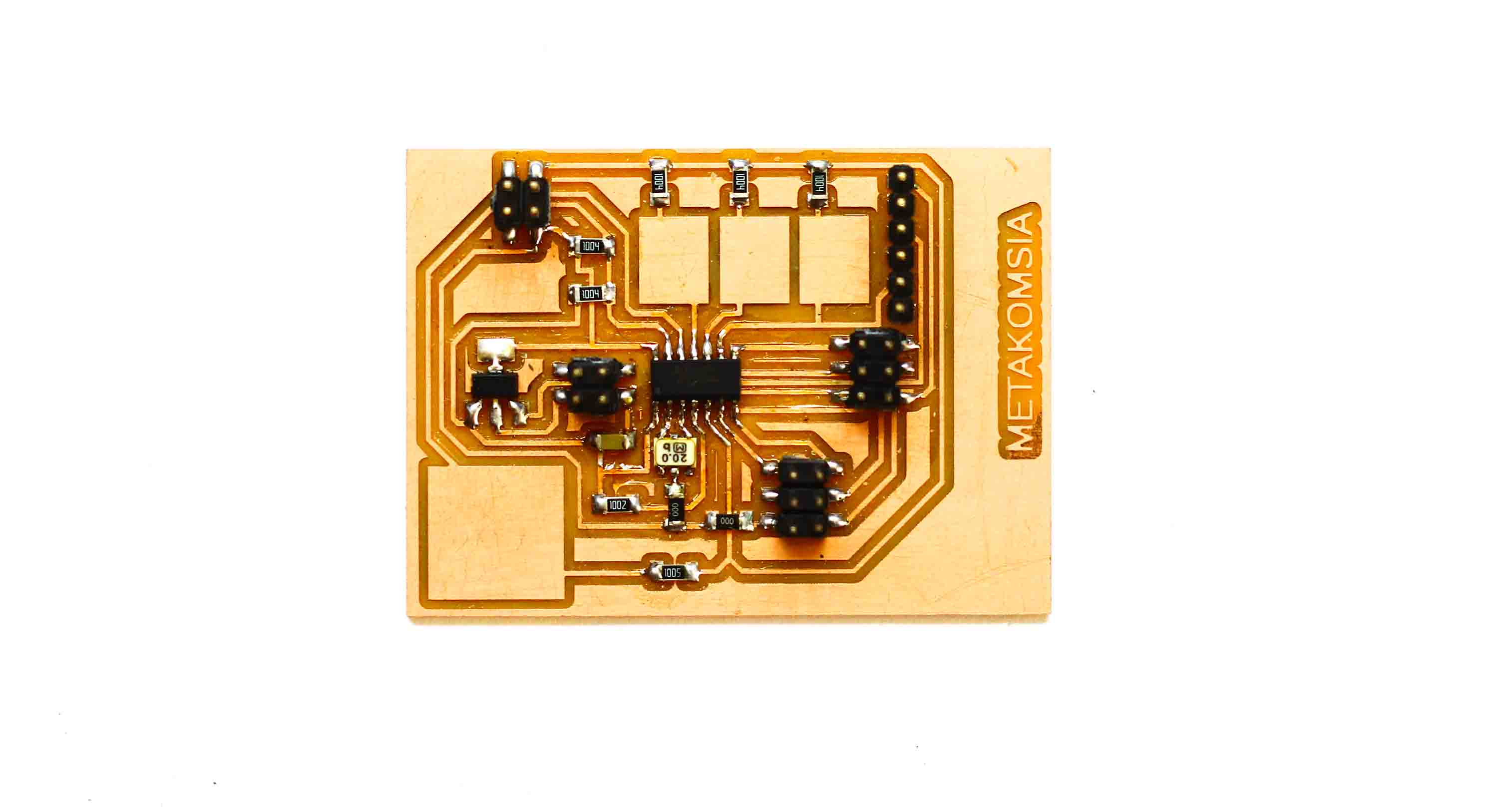
3. A modular board based on ATtiny 44 helped me in performing range of functions. For instance, same pin was used for driving motors and it was later used for sensors.
Output device without sensor
Understanding servos and initial run using arduino IDE
This week started on a bit of frustrating note. Most the things that I tried to do weren't working. The Arduino codes were not working either. I was just looking for a simple way to run the two servos. Neil's code did work in the end but I couldn't properly understand it. Hence, I made it a point to understand Neil'code and make my servos run.
A good place to understand servo motors is here . In short it is a DC motor with potentiometer and some electrical components. One good thing about servos it that you can control them through PWM. Hence, they will rotate when a voltage is passed and will stop when it isn't.
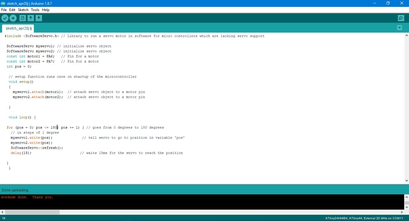
One thing of notice here is that, if you are using software servo library then you will have to change inside Softwareserial.h file a particular line otherwise an error will keep on coming. That line is "WProgram.h" and change it to "Arduino.h".
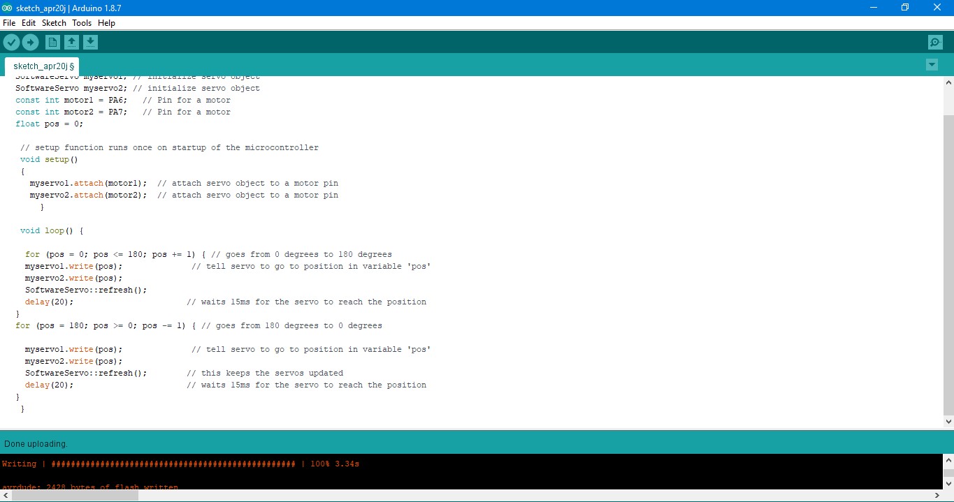
Now the servos were moving but the only issue I was now facing was that they were not rotating 180 degrees as expected. They were only moving like 120 degrees approx. This was only one for loop. But if you introduce another for loop that takes it back, it rotates 180 degrees. Also, the ideal delay should be 20ms because of 50 Hz cycle of the servo.
Driving Servos using embedded C
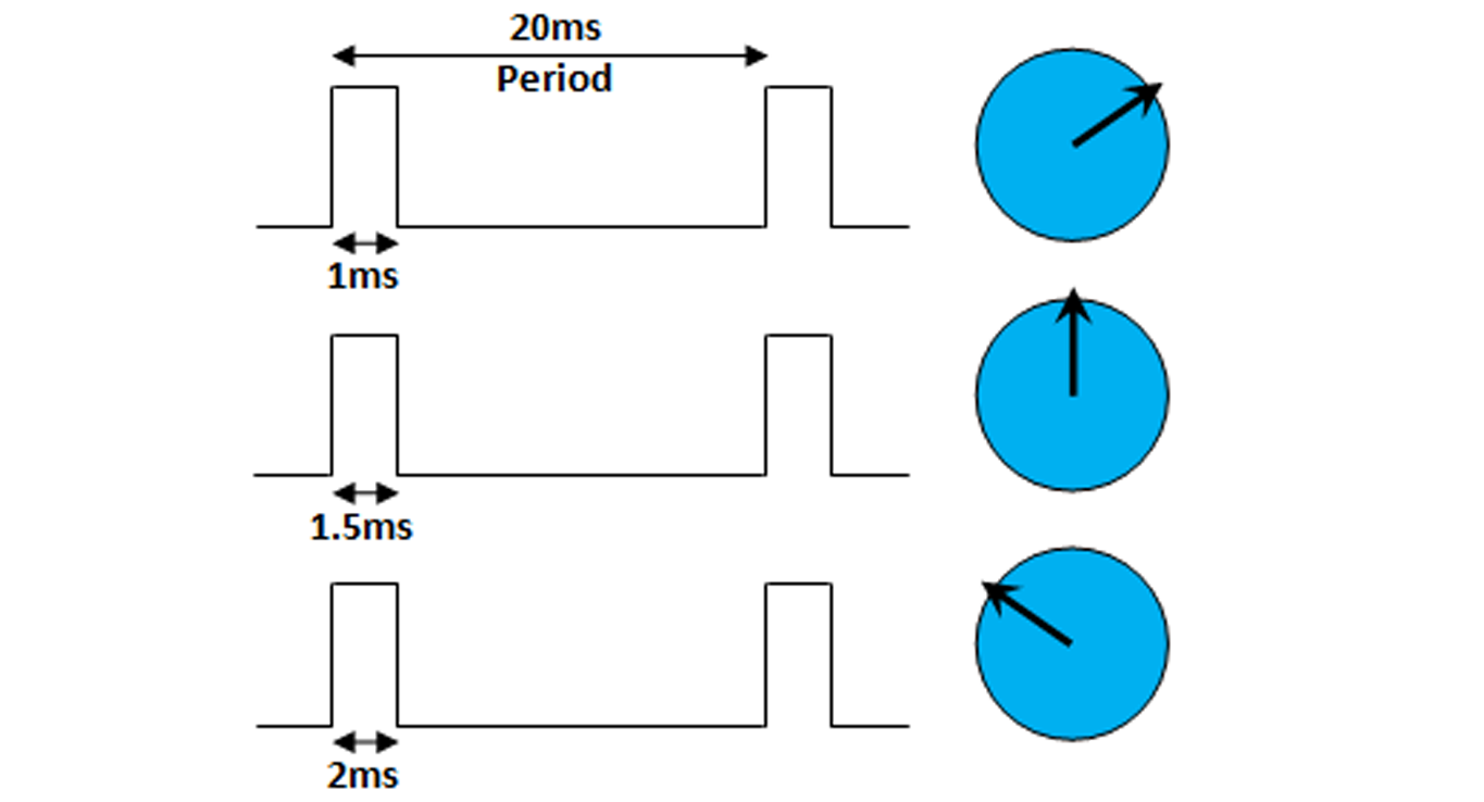
Next was to move on to Neil's code and try it. Probably doing the similar thing as above(rotating the servos by 180 dgrees) and modifying it further to do other things. I choose Neil's second code where you could rotate servos from the software side. At 1 ms, it remains at its position, at 1.5 ms it rotates 45 degree(mid-way) and at 2 ms it rotates 90 degrees. I preferred directly sending the code using Arduino IDE using the C file.
The highlights of this code are: 2 motors can be run simultaneously on two different PWM pins, hence those two PWM pins are defined initially,
#define PWM_pin_0 (1 << PA6)
#define PWM_pin_1 (1 << PA7)
If we want to run at the full 8MHz and not mess with the LFuse and avoid unintentional changes of clock frequency, a special write procedure must be followed. The CLKPCE bit must be written to logic one to enable change of the CLKPS bits. The CLKPCE bit is only updated when the other bits in CLKPR are simultaniosly written to zero. CLKPCE is cleared by hardware four cycles after it is written or when the CLKPS bits are written. Rewriting the CLKPCE bit within this time-out period does neither extend the time-out period, nor clear the CLKPCE bit.
//
// set clock divider to /1
//
CLKPR = (1 << CLKPCE);
CLKPR = (0 << CLKPS3) | (0 << CLKPS2) | (0 << CLKPS1) | (0 << CLKPS0);
From the data sheet(Page 32, table 6-11):
Next the while loop starts and inside while loop there are several for() loops. Each for() loop either rotates one or both the motors.
for (i = 0; i < loop_count; ++i) {
set(PWM_port,PWM_pin_0);
set(PWM_port,PWM_pin_1);
_delay_us(1000);
clear(PWM_port,PWM_pin_0);
clear(PWM_port,PWM_pin_1);
_delay_us(19000);
}
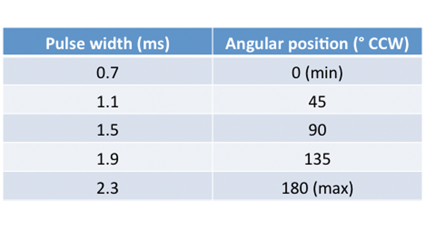
This particular code snippet turns both PWM pins on/high and sends a voltage for 1 ms/1000 us, just after that it sets both PWM pins off/low and stops sending voltage for 19 ms/19000 us. Since the frequency at which servos operate is 50 Hz/20 ms cycle and between 1-2 ms(I found later that you could run the servos at 0.7 ms and slightly above 2 ms also) .
for (i = 0; i < loop_count; ++i) {
set(PWM_port,PWM_pin_0);
_delay_us(1500);
clear(PWM_port,PWM_pin_0);
_delay_us(18500);
}
This particular code snippet turns only one i.e PA6 pin on/high and sends a voltage for 1.5 ms/1500 us, just after that it turns that pin off/low and stops sending voltage for 18.5 ms/18500 us.
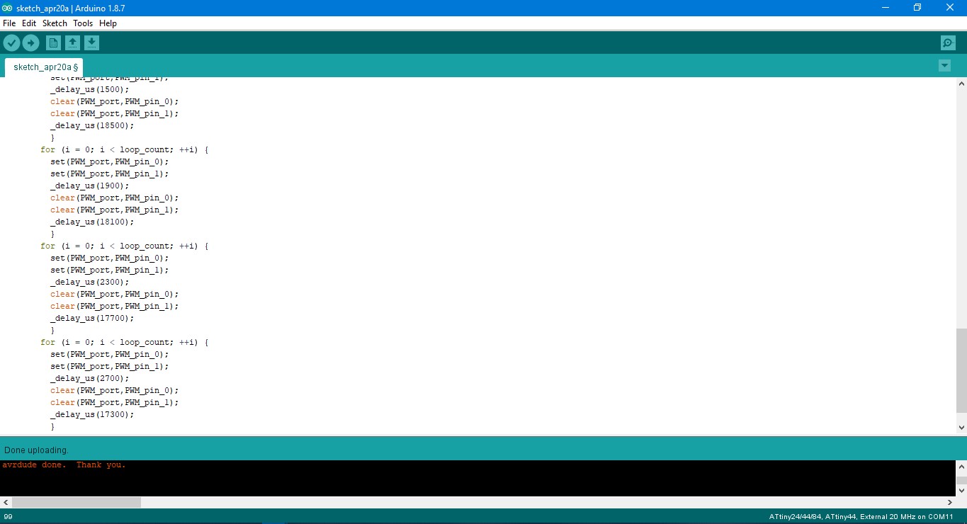
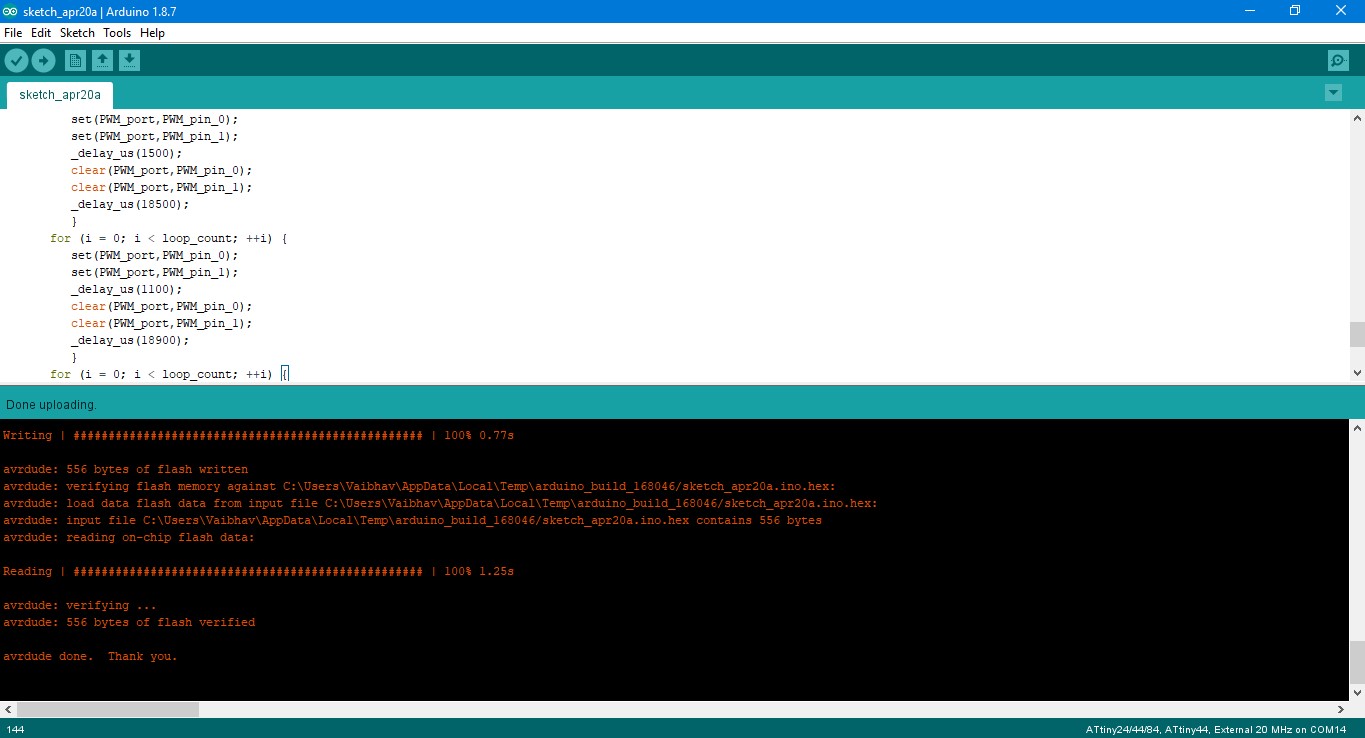
I modified Neil's code by starting the servos at 0.7ms (the extreme left position) and giving increments of 0.4 ms ending at 2.7 ms. This allowed the servos to turn 180 degree in 6 increments in counterclockwise direction, you can further reduce the difference between increments. The moment the loop reaches the last position(2.7 ms). Furthermore, I also added loops so that it goes in similar increments in clockwise direction. Check the illustration above. The only thing I couldn't understand was the function of the loop count in Neil's code, the moment I reduce it, the rotation speeds up and the moment you increase, it slows down. So, it can be said that each delay corresponds to a certain angle. The modified while() loop is written below:
while (1) {
for (i = 0; i < loop_count; ++i) {
set(PWM_port,PWM_pin_0);
set(PWM_port,PWM_pin_1);
_delay_us(700);
clear(PWM_port,PWM_pin_0);
clear(PWM_port,PWM_pin_1);
_delay_us(19300);
}
for (i = 0; i < loop_count; ++i) {
set(PWM_port,PWM_pin_0);
set(PWM_port,PWM_pin_1);
_delay_us(1100);
clear(PWM_port,PWM_pin_0);
clear(PWM_port,PWM_pin_1);
_delay_us(18900);
}
for (i = 0; i < loop_count; ++i) {
set(PWM_port,PWM_pin_0);
set(PWM_port,PWM_pin_1);
_delay_us(1500);
clear(PWM_port,PWM_pin_0);
clear(PWM_port,PWM_pin_1);
_delay_us(18500);
}
for (i = 0; i < loop_count; ++i) {
set(PWM_port,PWM_pin_0);
set(PWM_port,PWM_pin_1);
_delay_us(1900);
clear(PWM_port,PWM_pin_0);
clear(PWM_port,PWM_pin_1);
_delay_us(18100);
}
for (i = 0; i < loop_count; ++i) {
set(PWM_port,PWM_pin_0);
set(PWM_port,PWM_pin_1);
_delay_us(2300);
clear(PWM_port,PWM_pin_0);
clear(PWM_port,PWM_pin_1);
_delay_us(17700);
}
for (i = 0; i < loop_count; ++i) {
set(PWM_port,PWM_pin_0);
set(PWM_port,PWM_pin_1);
_delay_us(2700);
clear(PWM_port,PWM_pin_0);
clear(PWM_port,PWM_pin_1);
_delay_us(17300);
}
for (i = 0; i < loop_count; ++i) {
set(PWM_port,PWM_pin_0);
set(PWM_port,PWM_pin_1);
_delay_us(2300);
clear(PWM_port,PWM_pin_0);
clear(PWM_port,PWM_pin_1);
_delay_us(17700);
}
for (i = 0; i < loop_count; ++i) {
set(PWM_port,PWM_pin_0);
set(PWM_port,PWM_pin_1);
_delay_us(1900);
clear(PWM_port,PWM_pin_0);
clear(PWM_port,PWM_pin_1);
_delay_us(18100);
}
for (i = 0; i < loop_count; ++i) {
set(PWM_port,PWM_pin_0);
set(PWM_port,PWM_pin_1);
_delay_us(1500);
clear(PWM_port,PWM_pin_0);
clear(PWM_port,PWM_pin_1);
_delay_us(18500);
}
for (i = 0; i < loop_count; ++i) {
set(PWM_port,PWM_pin_0);
set(PWM_port,PWM_pin_1);
_delay_us(1100);
clear(PWM_port,PWM_pin_0);
clear(PWM_port,PWM_pin_1);
_delay_us(18900);
}
for (i = 0; i < loop_count; ++i) {
set(PWM_port,PWM_pin_0);
set(PWM_port,PWM_pin_1);
_delay_us(700);
clear(PWM_port,PWM_pin_0);
clear(PWM_port,PWM_pin_1);
_delay_us(19300);
}
}
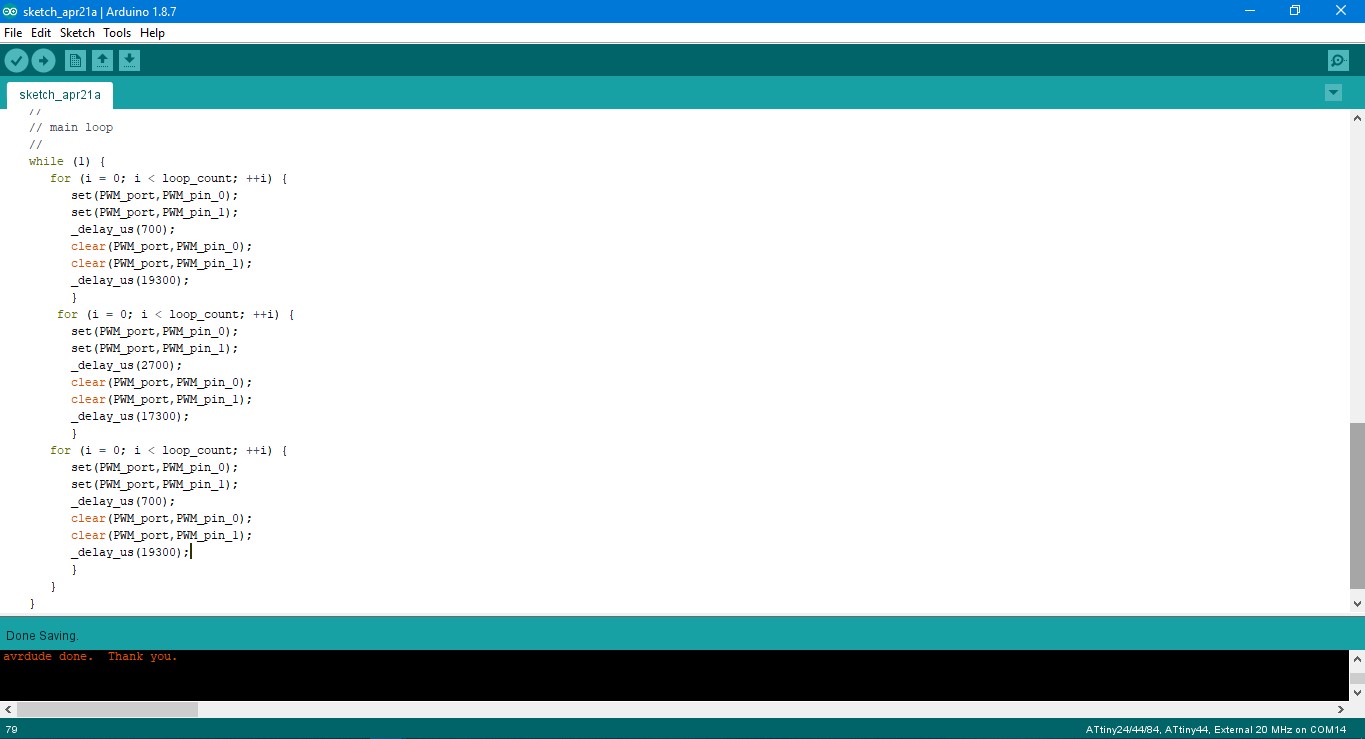
Next, I further modified the C code a little bit to remove the increments. In the previous code, I had increments of 4ms starting from 7 ms up untill 27 ms. In this particular code, the servos start from 7 ms, rotate 180 degree clockwise(27 ms) and then rotate 180 degree counterclockwise(7 ms)(illustration 7 and 8 above). The code is as follows:
while (1) {
for (i = 0; i < loop_count; ++i) {
set(PWM_port,PWM_pin_0);
set(PWM_port,PWM_pin_1);
_delay_us(700);
clear(PWM_port,PWM_pin_0);
clear(PWM_port,PWM_pin_1);
_delay_us(19300);
}
for (i = 0; i < loop_count; ++i) {
set(PWM_port,PWM_pin_0);
set(PWM_port,PWM_pin_1);
_delay_us(2700);
clear(PWM_port,PWM_pin_0);
clear(PWM_port,PWM_pin_1);
_delay_us(17300);
}
for (i = 0; i < loop_count; ++i) {
set(PWM_port,PWM_pin_0);
set(PWM_port,PWM_pin_1);
_delay_us(700);
clear(PWM_port,PWM_pin_0);
clear(PWM_port,PWM_pin_1);
_delay_us(19300);
}
}
Output device with sensors
Adding a sensor and controlling servo through it via Arduino IDE
The sensors are of two types, analog and digital sensors , analog sensors produce continuous values and digital ones produce discrete values i.e on(1) and off(0).
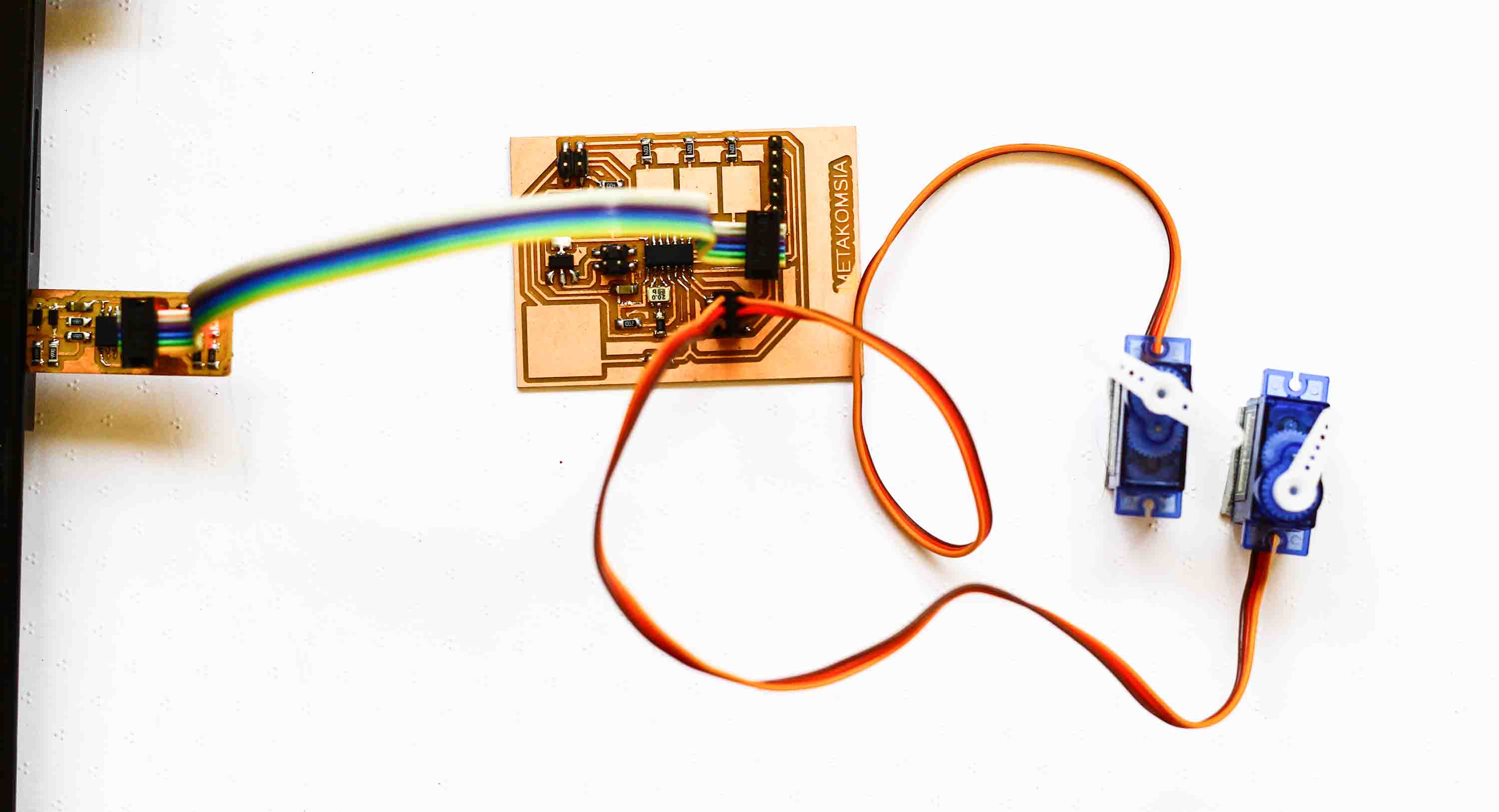
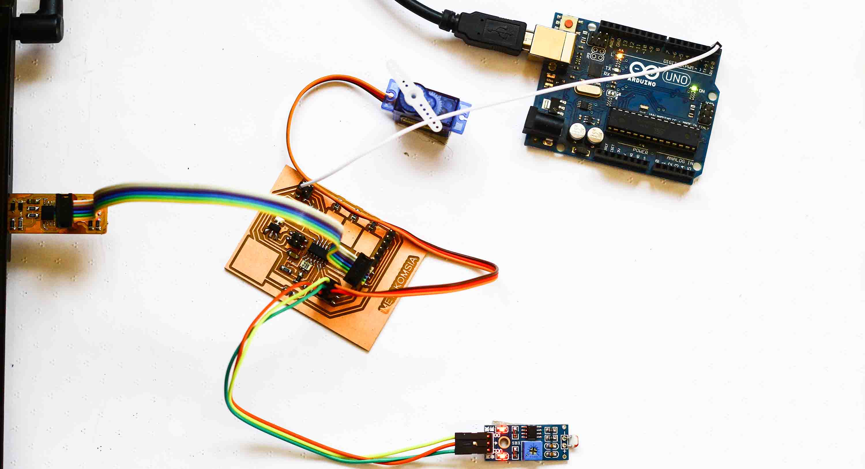
Now, I wanted to drive the servos using an sensor. Since the board was modular in nature, I could use on of the 3 pins I previously used to drive the Servos motors. I attached my LDR sensor (An LDR is a component that has a (variable) resistance that changes with the light intensity that falls upon it. This allows them to be used in light sensing circuits.) and made some changes in the Arduino code to drive it. I had previously noted down the values of LDR and I saw that there are only two values, hence you can create a if() loop that will help in running a for() loop rotating the servo when it receives light and stopping the servo when it doesn't receives light.
void loop() {
sensorValue = analogRead(analogInPin);
if(sensorValue < 50)
{
for (pos = 0; pos <= 180; pos += 1) { // goes from 0 degrees to 180 degrees
myservo1.write(pos); // tell servo to go to position in variable 'pos'
SoftwareServo::refresh();
mySerial.print("sensor value : ");
mySerial.println(sensorValue);
delay(20); // waits 20ms for the servo to reach the position
}
}
else
{
{
myservo1.write(0);
SoftwareServo::refresh(); // this keeps the servos updated
mySerial.print("sensor value : ");
mySerial.println(sensorValue);
delay(20); // waits 20ms for the servo to reach the position
}
}
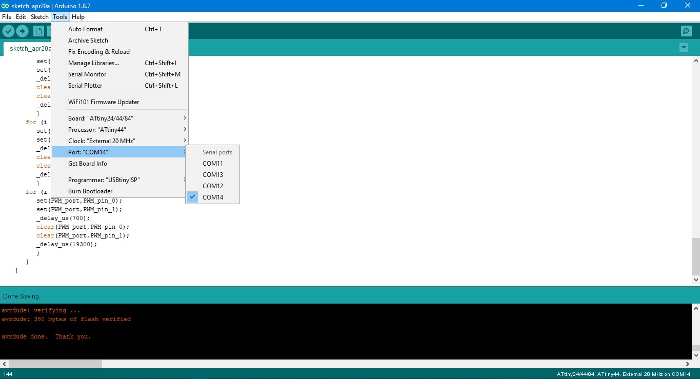
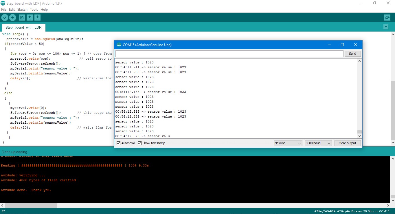
Serial Read from ATtiny 44: I tried using the FTDI cable to read the serial communication from ATtiny44 but I kept on failing due to some unknown reasons. I had to find another way to read the serial communication. Since Arduino has dedicated RX/TX pins and I can define my own RX/TX pins using software serial in ArduinoIDE. I defined pins PA1 for Rx and PA0 for Tx, though you will only need Tx to see what is going on in input sensor data. It also helps in debugging and creating if() statements. Next up, I uploaded the code using Arduino IDE to my board and uploaded a blank sketch to Arduino. Connect the Tx pin on your board to Arduino board. and open serial monitor with correct baud rate in Arduino's window. You will see the sensor values.
#define Rx PA1
#define Tx PA0
SoftwareSerial mySerial(PA1, PA0);
Sensors and servo programmed via Embedded C
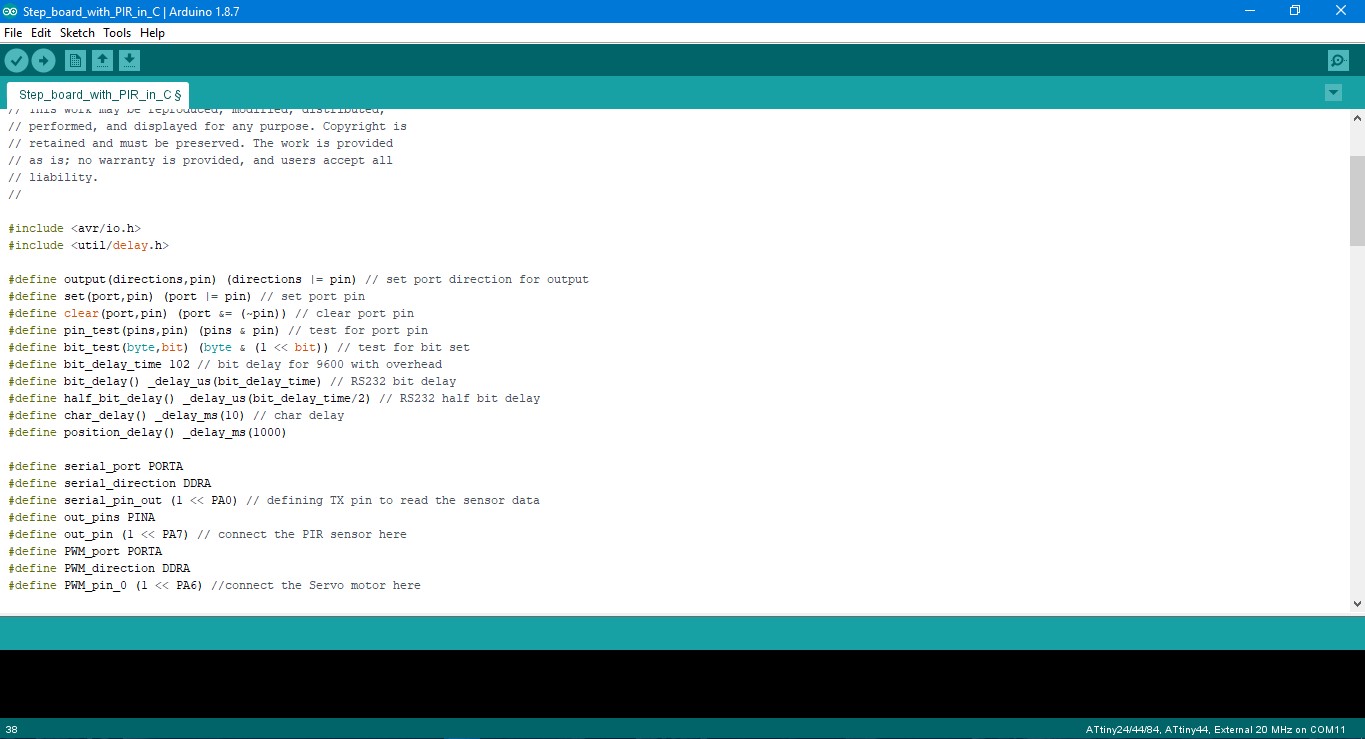
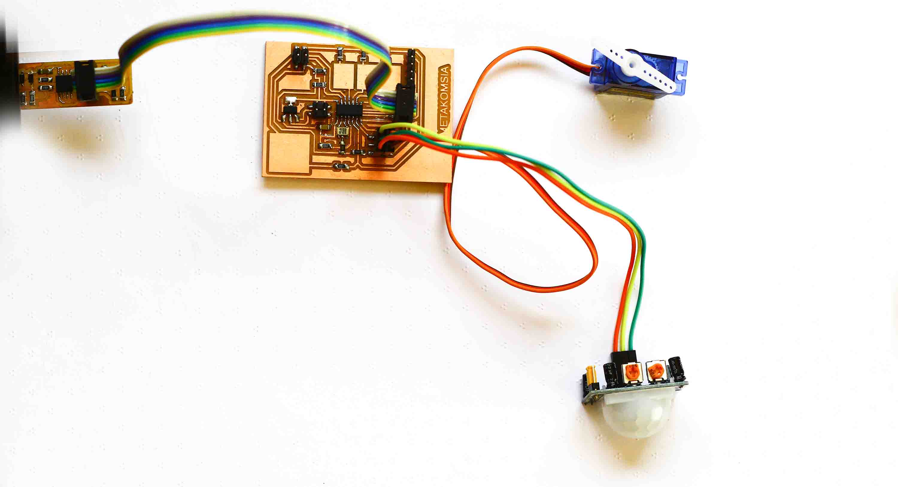
One of the last things that I wanted to try so as to slowly increase my grasp on Embedded C was modifiying Neil's code to sense using Passive Infrared Sensor(used as motion detectors) and run a servo motor. I took individual codes of PIR sensor and servo motor, combined them, made slight changes and added an if() statement. Since PIR sensor has only two values and is a discrete sensor i.e when it senses motion and when it doesn't senses motion. I only had to add an if() statement where it checks if there is any motion detected then rotate the servo motor 180 degrees, else if its not sensing any motion the servo is at rest. The following code defines the pins and ports for the designated functions:
#define serial_port PORTA
#define serial_direction DDRA
#define serial_pin_out (1 << PA0) // defining TX pin to read the sensor data
#define out_pins PINA
#define out_pin (1 << PA7) // connect the PIR sensor here
#define PWM_port PORTA
#define PWM_direction DDRA
#define PWM_pin_0 (1 << PA6) //connect the Servo motor here
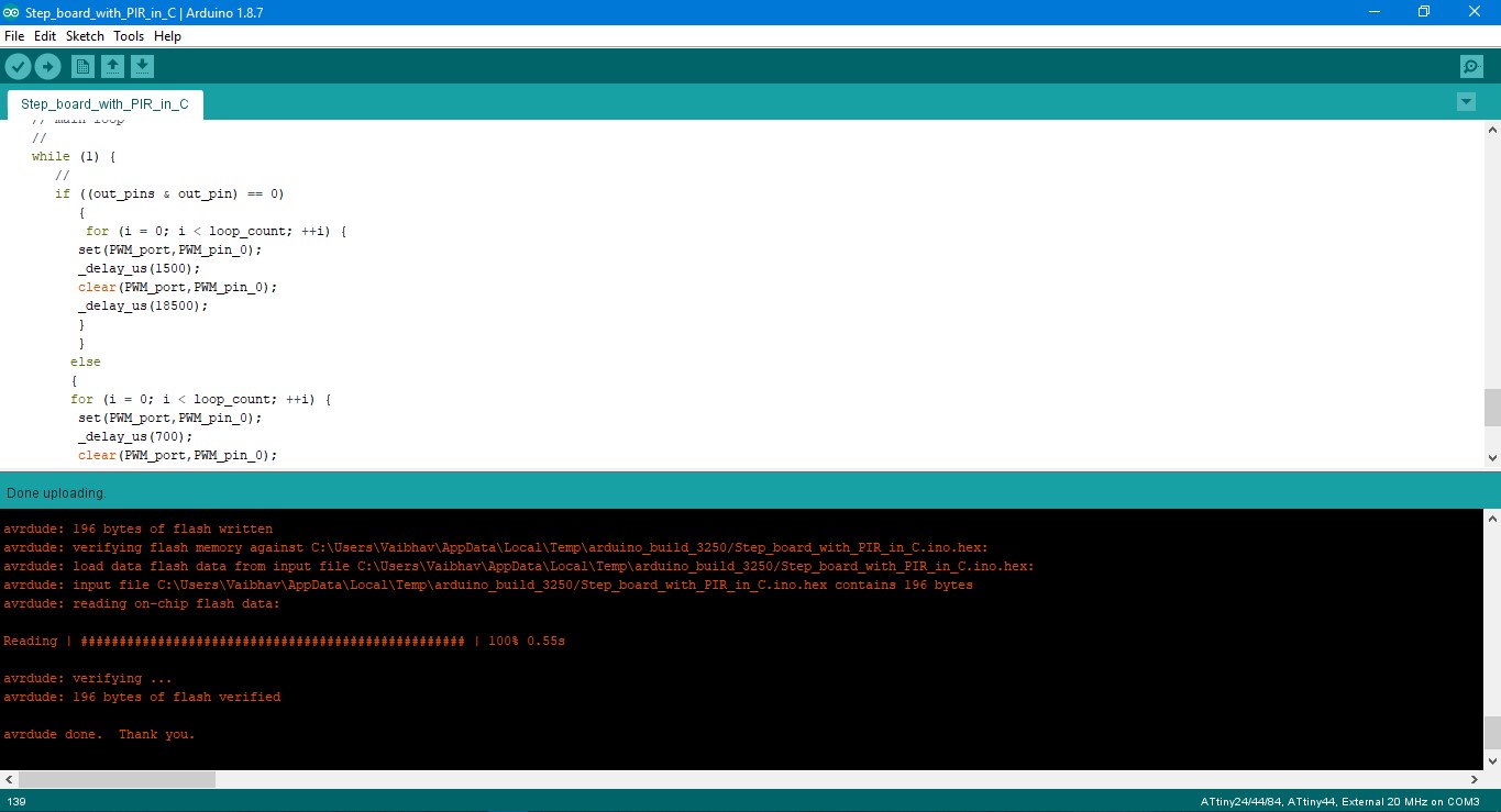
The main loop with if() statement is as follows:
while (1) {
//
if ((out_pins & out_pin) == 0) //checks if the there is any motion, 0 is no motion
{
for (i = 0; i < loop_count; ++i) {
set(PWM_port,PWM_pin_0);
_delay_us(1500); // this keeps the motor in the midway position at rest
clear(PWM_port,PWM_pin_0);
_delay_us(18500);
}
}
else
{
for (i = 0; i < loop_count; ++i) {
set(PWM_port,PWM_pin_0);
_delay_us(700); // this take the motor to the extreme left
clear(PWM_port,PWM_pin_0);
_delay_us(19300);
}
for (i = 0; i < loop_count; ++i) {
set(PWM_port,PWM_pin_0);
_delay_us(2700); // this take the motor to the extreme right
clear(PWM_port,PWM_pin_0);
_delay_us(17300);
}
}
}
}
Download all the codes for this week, here.
1. LDR with servo
2. Servo motor rotating 180 degree
3. Servo motor
4. Servo motor six increments
5. PIR with servo
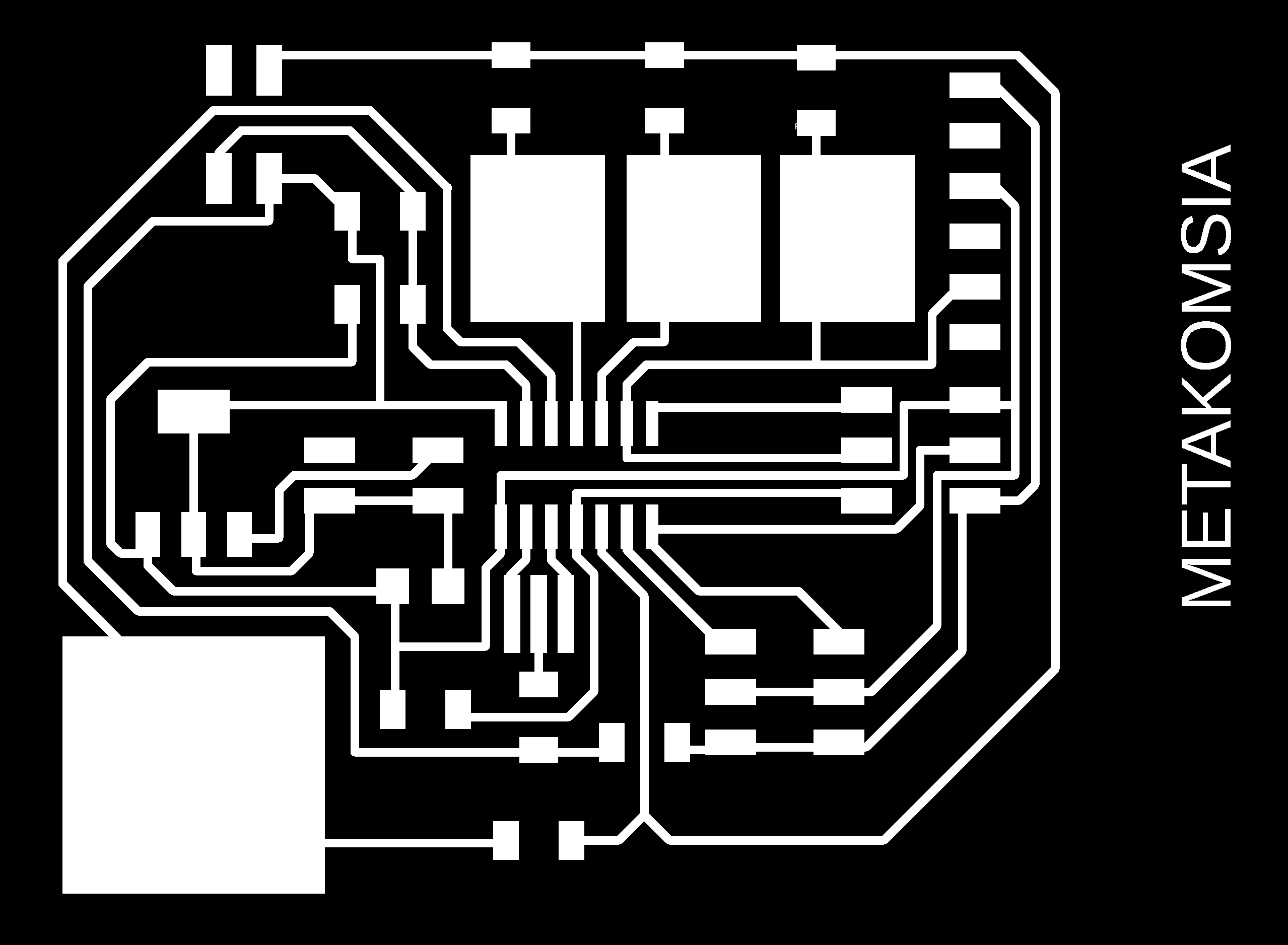
Download the design files for this week, here
1. Outline
2. Traces